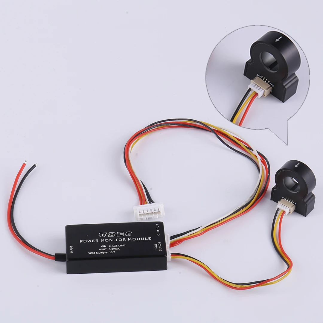
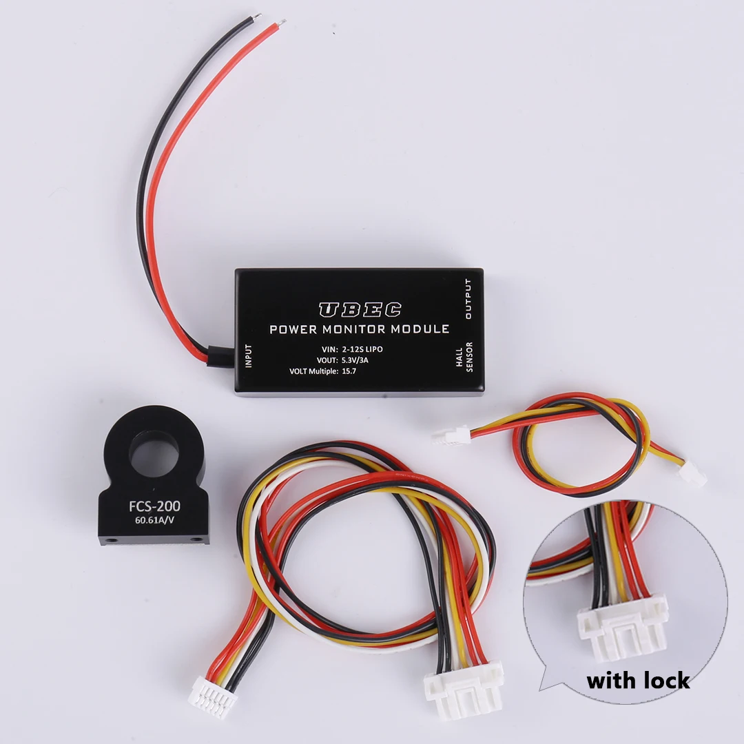
The Hall current and voltage meter adopts the separation design of the main module and the hall sensor. The main module provides UBEC 5.3v power supply and high-precision resistance 1 / 15.7 partial voltage output to detect the input power voltage function. The hall sensor is responsible for detecting the circuit current to be measured by non-contact induction. The hall sensor has built-in digital processing circuit and built-in reference.
Product parameters: Power Monitor
UBEC main module:
Input voltage: 2s-12s lipo (max60v)
Output voltage: 5.3V/3A
Partial pressure detection: 15.7
Dimension: 25 * 51 * 10mm
Weight: 15g
Hall sensor:
Power supply voltage: 5V(土0.3)
Detection ratio: 60.61A/V
Detection reference: 0.825V/50A
Dimension: 22 * 26 * 8.5mm
Threading hole diameter: 10mm
Installation hole distance: 17mm
Weight: 11g
(there will be some errors in the manual measurement, and the actual object shall prevail.)
Note:Although the maximum input voltage of the main module can reach 60V, the detection voltage can only be about 51.8v on the main control of 3.3VADC system, that is, the voltage of 12s lithium battery; the hall sensor adopts 5V regulated power supply, otherwise the detection accuracy will be affected.
Hall calibration instructions
The calibration of Hall sensor is divided into static calibration and ratio calibration. Static calibration refers to returning the output signal to zero when the input current is 0. Ratio calibration refers to setting the output signal at 0.825v under the condition of input standard 50A current, so as to fix the current ratio of Hall sensor as 50 / 0.825 = 60.61a/v Power Monitor.
The static calibration results will affect the ratio calibration results, so a static calibration must be conducted before the ratio calibration, and the static calibration only needs to meet the power supply of 5V and the current of 0, which can be calibrated at any time, and the result does not affect the ratio parameters.
Calibration conditions
1. Standard 5V power supply;
2.the standard 50A current source can be formed, which can be 5a, 10a, 25A, 50a, 5A. It is the way that the detection line is wound 9 times on the sensor to get a current source with 10 times current. 10A is wound 4 times and 25A is 1 circle. The more turns are wound, the greater the cumulative error is. Therefore, the 25 or 50A current source should be used as far as possible.
3. Connect the calib pin of Hall sensor to ground with a calibration switch (other methods that can provide low level can also be used)
4. Static calibration: under the condition that the detection line current is 0, press the calibration switch twice in Power Monitor For Cube Orange.
The following is a comparative test of the Hall current data read by flight control and the test data of professional instruments. Due to the limited equipment, the test line is wound 4 times on the hall to form the output current data of X5 times of the test current.
Product Photograph






Reviews
There are no reviews yet.